TileLogicTM             
 
Menu

DXF OUTPUT OPTIONS

DXF OUTPUT OPTIONS
 
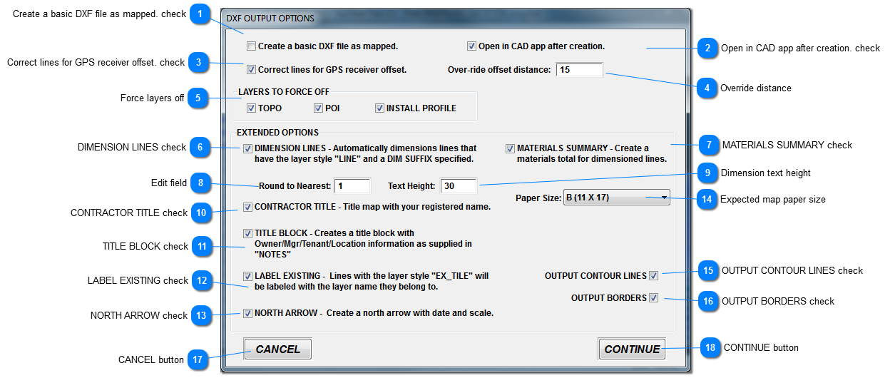
DXF options are available to increase productivity when creating CAD file as-builts.  Once imported into CAD software, these items are editable.
1

Create a basic DXF file as mapped. check

1. Create a basic DXF file as mapped. check
 
Simply creates a DXF with no Extended options, even if they are checked.  This provides a quick output for use with CAD templates, or when only the mapped info is needed with no extended features.
 
2

Open in CAD app after creation. check

2. Open in CAD app after creation. check
Will attempt to open the default CAD program, after DXF creation, and load the DXF.
 
3

Correct lines for GPS receiver offset. check

3. Correct lines for GPS receiver offset. check
Automatically moves lines back to correct for GPS receiver offset.  This distance is saved with the data, and set according to the machine which was used to install.
 
4

Override distance

4. Override distance
 
When no GPS receiver offset distance was saved with the data (offset = 0) use this as default.
 
5

Force layers off

5. Force layers off
These layers will always be created in the DXF, but by checking them, by default they will be turned off in the CAD software.
 
6

DIMENSION LINES check

6. DIMENSION LINES check
 
Lines will be dimensioned automatically when checked.  If not checked, a materials summary cannot be created.
 
7

MATERIALS SUMMARY check

7. MATERIALS SUMMARY check
 
When lines are automatically dimensioned,  a material summary listing is generated, when checked.
 
8

Rounding of Dimensions

8. Edit field
 
Dimensions may be rounded, specify round to nearest here.  i.e. Setting this to "5", and dimensions will be rounded as such; 100, 105, 110 etc.
 
9

Dimension text height

9. Dimension text height
Height of text, in feet for dimensions on tile lines.  Recommended to use a value approximately 1/3 the lateral spacing installed.
 
10

CONTRACTOR TITLE check

10. CONTRACTOR TITLE check
 
 
11

TITLE BLOCK check

11. TITLE BLOCK check
 
Generates a title block, using information specified in the Field Notes window.
 
12

LABEL EXISTING check

12. LABEL EXISTING check
Only lines with "LINE" style AND suffix will be dimensioned.  Lines with EX_TILE style are not dimensioned, as they are considered "pre-existing".  However, checking this box, will label them with the layer name.
 
13

NORTH ARROW check

13. NORTH ARROW check
 
14

Expected map paper size

14. Expected map paper size
 
Allows for DXF scale generation based on your expected paper size.  This does not tell CAD what paper size to print with, that must be specified in the software.  It simply sets a scale, and map, best suited for the paper size you expect to use.  Choices are A, B, C, or D size.
 
15

OUTPUT CONTOUR LINES check

15. OUTPUT CONTOUR LINES check
 
Contour lines may be output to DXF, based on current Map Contour settings.  Note, that clipping to borders is not available with DXF output, and must be done in CAD software manually.
 
16

OUTPUT BORDERS check

16. OUTPUT BORDERS check
 
Border of type "Property" will be output when checked.  Clipping boundaries are ignored, as they have no meaning in DXF output.
 
17

CANCEL button

17. CANCEL button
 
Cancels DXF creation.
 
18

CONTINUE button

18. CONTINUE button
 
Proceeds with DXF creation.