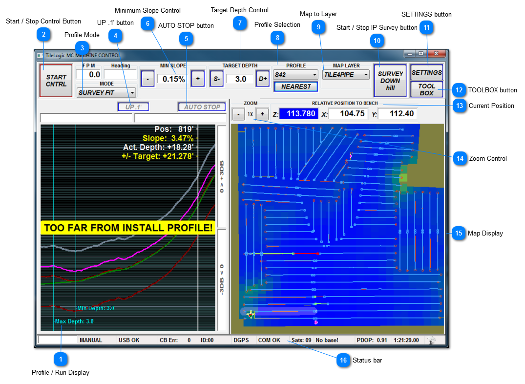
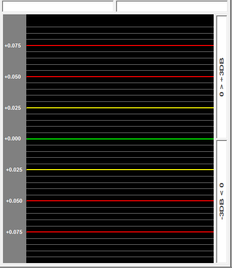
MC MACHINE CONTROL window
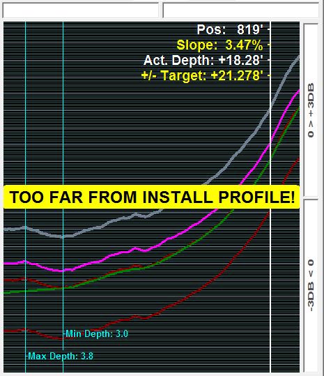
 Profile / Run Display
This display may be resized by left clicking (hold down) on the right border and dragging right or left.
|
|
 Start / Stop Control Button
 Toggles Automatic control. [ALT+C]
The Start / Stop control also has the same functionality as the LOG DATA button in mapping mode. That is, anytime you start control, you also start logging of map data.
|
|
|
 Profile Mode
Profile Selection of NONE
"SLOPE ONLY" mode available. A basic graph screen will be shown, the control runs a slope only profile, using min slope, similar to a laser. Target depth has no effect.
Profile Selection of IP Survey (prefix "S")
"SLOPE ONLY" mode available. Profile screen with install pass (IP) survey data. The min slope is calculated as the target.
Profile Selection of network profile (prefix "N").
"SLOPE ONLY" mode available. Profile displayed with topo data from prior surveyed data. The min slope is calculated as the target.
|
|
 UP .1' button
 By clicking, "bumps up" the current target elevation by .1' and recalculates target to end of line. [ALT+U]
|
|
 AUTO STOP button
 Clicking this will end control in the distance specified by Tile Offset. [Alt+A ] [SPACEBAR]
|
|
 Minimum Slope Control
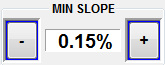 The minimum slope you wish to run. When profile mode is "SLOPE ONLY", this is THE slope that's ran.
- to decrease by .01 [-]
+ to increase by .01 [+]
|
|
 Target Depth Control
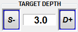 The target depth. This value has no meaning when profile mode is "SLOPE ONLY" or "PER DESIGN"
S- to decrease by .1' [S]
D+ to increase by .1' [D]
|
|
 Profile Selection
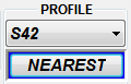 Select the drop down box to select a profile. Profiles with the prefix "S" denote IP survey passes. Profiles with the prefix "N" denote network (Landrain tm) which have been pre-designed. These network pipe designations include pipe numbers in parenthesis. Example: N1(1-10). Network profile 1, includes Landrain tm pipe numbers 1 through 10.
The NEAREST button selects the closest loaded profile (either IP survey or network) to the current location. [ALT+N]
|
|
 Map to Layer
 Select the current mapping layer. This may be changed "on the fly".
|
|
 Start / Stop IP Survey button
 Toggle survey start / stop. The survey direction depends on the setting in the user preferences.
|
When a survey is completed, the surveyed profile is automatically loaded as the current profile.
|
|
|
 SETTINGS button
|
|
 TOOLBOX button
|
|
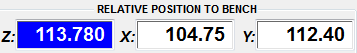
 Current Position
Current position coordinates relative the the current Bench location.
|
|
 Zoom Control
-
- Zoom out [PGUP]
-
X Magnification factor
-
+ Zoom in [PGDN]
Zoom relative to current location (shown by cursor location). Max zoom = 64X.
|
|
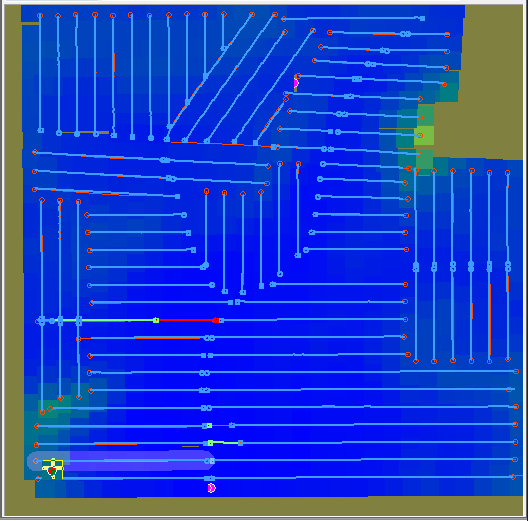
 Map Display
This display may be resized by left clicking (hold down) on the left border and dragging right or left.
|
|
 Status bar
|
|